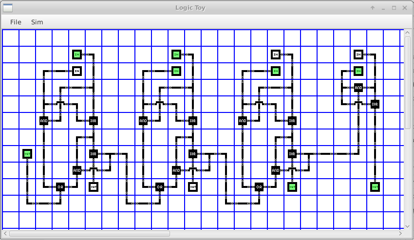
I had an idea for a game, part of which needed a grid based logic simulation, so I wrote a prototype logic engine. As these things tend to do, it kinda took on a life of its own. The basic premise is that each edge of a tile (North, East, South and West) can be ONE of nothing, an input or an output.
While Wire "gates" (for connecting things) have only one input then can have multiple outputs to allow branching of a signal. Cross or bridge gates allow a cross roads, keeping the horizontal and vertical signals separate. Input gates are the only gate that you can interact with and act as the circuits inputs, you can toggle the state of the input by right clicking it.
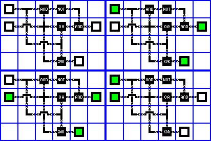
While there are still some areas needing work, its already rather functional. The four images above show a circuit with every permutation of its inputs. The four logic gates at the top of the circuit (AND x2, NOT, OR) replicate an XOR gate. As you can see the output matches the output of the XOR logic gate. This shows that both the XOR gate and also a simple circuit combining different logic gates also works.
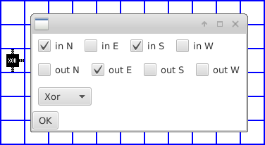
Editing a circuit is straight forward, as you can see from the picture, its just a case of selecting where the inputs and outputs are and what logic function should be used.
I'd be interested to hear feedback or ideas, grab it here Enjoy!
Proof 12+7=19!