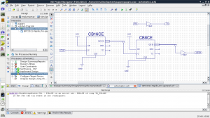


After a lengthy break from electronics (blame the wife!) I decided to get back into working with FPGA's and the world of pain that are their woeful accompanying tools... You can see from my earlier posts that my introduction to VHDL allowed me to produce (from scratch!) a VGA signal generator, I was left feeling that (for me personally) VHDL was not the most intuitive way of designing a circuit and I promised myself that I would have a good look at using schematic capture (basically its turning a diagram of logic blocks into VHDL). For my first trial - and that's what it was! I decided I'd make a simple circuit just to flash the Papilio Pro's onboard LED a couple of times a second. I still don't know what it was that was holding me up for quite some time, but temporarily replacing one of the counters with a larger one fixed the problem. Once I swapped the counter back it was still working - like it should have been all along! (I'm guessing I might have to get used to the odd bit of random behaviour) Anyhow the basic design was simple, count the boards 32mhz clock pulses with a large enough counter and use a fairly high bit of the counters output as a driver for the LED. Take a quick click at the image above it might help follow whats going on. A 32mhz clock has a period of 31.25ns my first guess at how many bits I'd need was spot on, the high bit of an eight bit counter driven by the high bit of a sixteen bit counter... According to WolframAlpha 31.25ns * (2^24) comes out at just over half a second which puts us in the ballpark of perceivable flashing. Now you'd have thought that a really very basic circuit like this could have been implemented even by a newbie in what 10 minutes? I wish! Aside from the circuit behaving badly in real life and simulation then the same circuit partly rebuilt working - there is the little *gem* of bus taps.... Bus taps are should be a simple a way of getting (in this case) just one signal from a bus of say sixteen signals. The big gottcha is making sure that "automatically add a bus tap between the bus and wire" is set in the add wire options. It doesn't actually seem to do anything when you create the bus, but it does mean that it will allow taps to be added to it, if you've not selected this option who knows if you can do it without destroying and recreating the bus first! Actually placing the tap isn't particularly intuitive either, first you have to click with the centre of the bus tap to select the bus, then you have to move the head of the bus tap exactly onto the bus and click again. Basically the whole process is a needless ball ache (and I'm being polite here!!!) But wait there's more! (pain) It took me further time and frustration to discover that the bus name and the outgoing wire (net) both have to have the same name ie: COUNT_2_OUT(7:0) --> (the tap) --> COUNT_2_OUT(7) It took me a while for this to dawn on me sadly... (the warnings showed a problem but could have been a LOT more useful) this seems to mean that if you want to keep an output named for example LED1 (in your constraints for example) you seem to need to put a buffer between the wire coming out of the tap and into the output marker. I wish that were all the frustrations with their bad advert, but Xilinx's tools are far from eXcillent with a wide range of glitches and really awkward interface design choices. There was some good news mind, after I got my flashing LED, I decided to tie TX and RX of the USB serial channel together, just to see if I'd get anything back over USB. To be honest between Xilinx tools and potential configuration issues with the laptops ttyUSB I wasn't over hopeful! but get this - it work first time - no really, I was so shocked I had to throw an inverter into the mix to check I got rubbish back for fear it was just a local echo! So my conclusions - well I think you know my thoughts on Xilinx's tools - its a shame they don't grok the advantages of open source, it would improve their tools and make them a bunch more money, but ah well I digress - I definitely do see the advantage of using schematic capture (for me personally its a lot more intuitive) and my next task I'm going to set myself is converting a VHDL snippet into a working library symbol (I'm thinking UART here) - Wish me luck! :)