So our second adventure with a FPGA begins... however I'll not be providing a complete solution for you as I normally would, why? :-o Well I kina see a VGA controller as a rite of passage for FGA skills.
Like bit banging a PAL signal with a micro controller you need to be spot on with timings and their relationships...
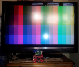
The first gotcha to avoid before even connecting your board is to connect it to the most capable video card you can, many of the newer monitors / cards / laptops and especially small TV's with VGA ports can't do the "traditional" VGA resolutions of yesteryear. In the end I just plumped for 1680x1050 even TV's that can't quite manage it usually are able to down scan the signal, and although it won't look the best at least it'll work!
A later refinement to a VGA controller might be to enable frequency changing on the fly, but lets leave that for later... Now the one downside of the widely usable HD resolution is it's dot (pixel) clock. At 147.14mhz you might need another clock signal to run other components, but then who know you might be able to get all your components running at that rate (depending on complexity etc)
Another general gotcha is making sure that your clock is working correctly, now obviously if you stick 147mhz through led1 you'll just see a fairly bright led but no clue if you are in the right ball park... (of course an oscilloscope is cheating - I really must treat myself some day!) don't forget you can simulate all you like but given as you supply the clock signal in code...
What I'd suggest is that you count frames, given a 65hz or so frame rate if you count 32 or so frames and invert the state of led1 (make it a buffer signal not an output signal) then you'll get a 1hz flash, which you can see by eye that you are roughly in the right ball park.
You'll no doubt using the IP generator to produce the requisite frequency, just don't forget to define the component in your code and to actually instance it ... ho hum.... ahem... cough...
in the architecture block (check the generators instancing template)
component clockTile
    port (  CLK_IN1     : in    std_logic;
            CLK_OUT1    : out   std_logic);
end component;
and after you have begun your behaviour...
clock_tile: clockTile port map(CLK,dotCLK);You can use CLK from the 32mhz pin and make your process sensitive to dotCLK Because you might need to modify timings and you might want to comment out (working) frequencies and have a whole different resolution handy in code, then a set of constants are useful, bare in mind horizontal timings are in pixels (dot clock pulses) and vertical timings are in lines... (htTot * dotCLK...)
-- dotclk 147.14
    constant htVis  : integer  := 1680;   -- pixels
    constant htFP   : integer  := 104;
    constant htSync : integer  := 184;
    constant htBP   : integer  := 288;
    constant htTot  : integer  := htVis + htFP + htSync + htBP;

    constant vtVis  : integer  := 1050;   -- lines
    constant vtFP   : integer  := 1;
    constant vtSync : integer  := 3;
    constant vtBP   : integer  := 33;
    constant vtTot  : integer  := vtVis + vtFP + vtSync + vtBP;
using constants like this mean you can do things like this...
if hcounter>htVis-1+htFP and hcounter<htVis+htFP+htSync then
    hsync<='1';
else
    hsync<='0';
end if; -- do the hsync
The Front and Back Porch (htFP and htBP) are simply delays before and after the sync pulse.
after you have done the visible lines you don't need hSync pulses for the blank lines and you just need to wait through the porches and do the sync pulse...
My first attempt wasn't a great success I had a brain burp and thought it would be interesting "idea" to use a state machine to handle the timings and pattern generation - take it from me that's an experiment that probably won't make for an especially fulfilling experience.
I'd also recommend dealing with hsync/vsync first in one block of code, then separately in another block deal with pattern generation, if you munge the all the functions in together odds on you'll run into problems. I'd even deal with the counters separately to the sync pulse. Many monitors will tell you when they detect a valid VGA signal so initially you don't even need a pattern...
While on the subject of pulses a negative sync pulse is high when inactive and low when active, with a positive sync pulse being as you'd normally expect a signal.
You'll probably have a few false starts, a soupçon of frustration, and a whole bunch of smug satisfaction when you get it licked, I've also even given the horribly verbose nature of VHDL you should be able to produce a VGA pattern generator with less code that you thought!
Enjoy!