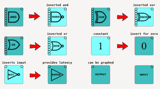
For a little while now I've been working on cLogicFun, and while its far from perfect and definitely a work in progress you can do quite a bit with it. There are a number of examples provided but first lets take a look at the different "nodes" you can add to your circuit. AND, OR, NOT and XOR are as you'd expect just conventional logic gates, however you can edit a few different properties one important one is whether the gate should be inverted. As an aid to readability (as you can see from the image), the node changes its appearance to make it obvious that its function has changed. While the application doesn't prevent you from inverting or adding latency to an input or output this is not recommended... Speaking of the input node to toggle an input nodes state simply right click on it, this is the only means of user interaction with a circuits operation, short of actually changing the circuit itself.

We've already touched on invert, latency bares some explanation, this determines how long it takes (in simulation "ticks") for a change in input states to effect the output of the node. Obviously this is a lot more convenient that adding multiple buffers if you want to delay some signal for use in a later stage of a circuit. Rotation if fairly obvious and can be useful when organising your circuit to make it look at least fairly tidy. Text allows you to add a label to a node, which can be very useful in terms of clarity, for example you might use a label of "anding B . D . ~C" just so you know what its doing without having to trace it's input wires. Labelling is also useful when using the rudimentary output graphing facility (its an ugly work in progress!)

Connecting nodes is done using wires, creating a wire is just a matter of dragging from a nodes output and dropping it on an input. Unlike real logic gates all nodes only operate on inputs with connected wires, for example if you had a real 4 input AND gate you'd have to set each input high to get a high on the output, with an AND node only inputs with connected wires need to be high, unconnected inputs are disregarded.
If you connect a wire to an input that already has a wire the existing wire will be deleted, clicking a wire at its end (where it connects to an input) will also delete a wire. You can drag new wires out of an output as many times as you like creating multiple wires all starting at the same output.
This leads me to the biggest problem with wires, when I started the project I though a bunch of curved lines would look neat, like some great patch board, however things can easily get out of hand! The image of wires you can see is a small part of a simple 4 bit counter, and that forest of wires sure aint pretty ! Its not completely unusable but it will be replaced with something before long, I'm currently leaning towards more conventional wires which you must route yourself with joints and non connecting wires represented as you would expect with a more traditional circuit diagram, but I'm certainly up for hearing suggestions...
There are a number of examples available with the application
My first functional circuit after testing very simple combinations of inputs and gates was a 4 bit adder it allows you to enter two 4 bit values with input nodes and see the result on five output nodes (1 node is for overflow)
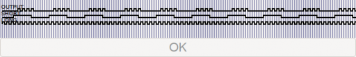
There are two versions of a flasher circuit that makes 4 short flashes followed by a long pause then repeats, the reason there are two versions is that the first version was created before I implemented node latency, as a result the first version has 7 buffer nodes to help create the long pulse. In order to create a clock signal the NOT node comes into play, by feeding back its output back to its input you get an oscillation. As you can see by the second version of the flasher, I've been able to do away completely with extra buffers and simply rely on extra latency in one of the NOT gate (I told you the "graph" needs more work!)
There is an example demux circuit which given a 2 bit binary input "switches on" one of four outputs, multiplexing is demonstrated by switching one output between two different sources
Latches are really important in digital design and despite my initial success with an SR latch, I struggled with creating a flip flop forgetting completely that you need two latches for a flip flop thankfully the creator of Digital was generous enough to help me get flip flops straight - it been a while! On the subject of Digital I'd heartily recommend using it, especially if you're wanting to do some real design work, its a much more mature project and far more capable than my nascent offering...
Having implemented a Master Slave latch creating a counter was quite straight forward, however given that its a great mess of wires that definitely what's lead me to my dissatisfaction with the current state of wires
Saving of circuits is done to XML files, with a 46 node, 91 wire circuit the counter circuit ends up being just 22KB which isn't too bad for an ASCII format
While there is still plenty of things that need finesse and loads of potential new features, (not least sub circuits as nodes) the current state of cLogicFun is one where you can actually design functional circuits and see them working. Please do try it out and I'd welcome constructive ideas on how it can be improved.
Enjoy !