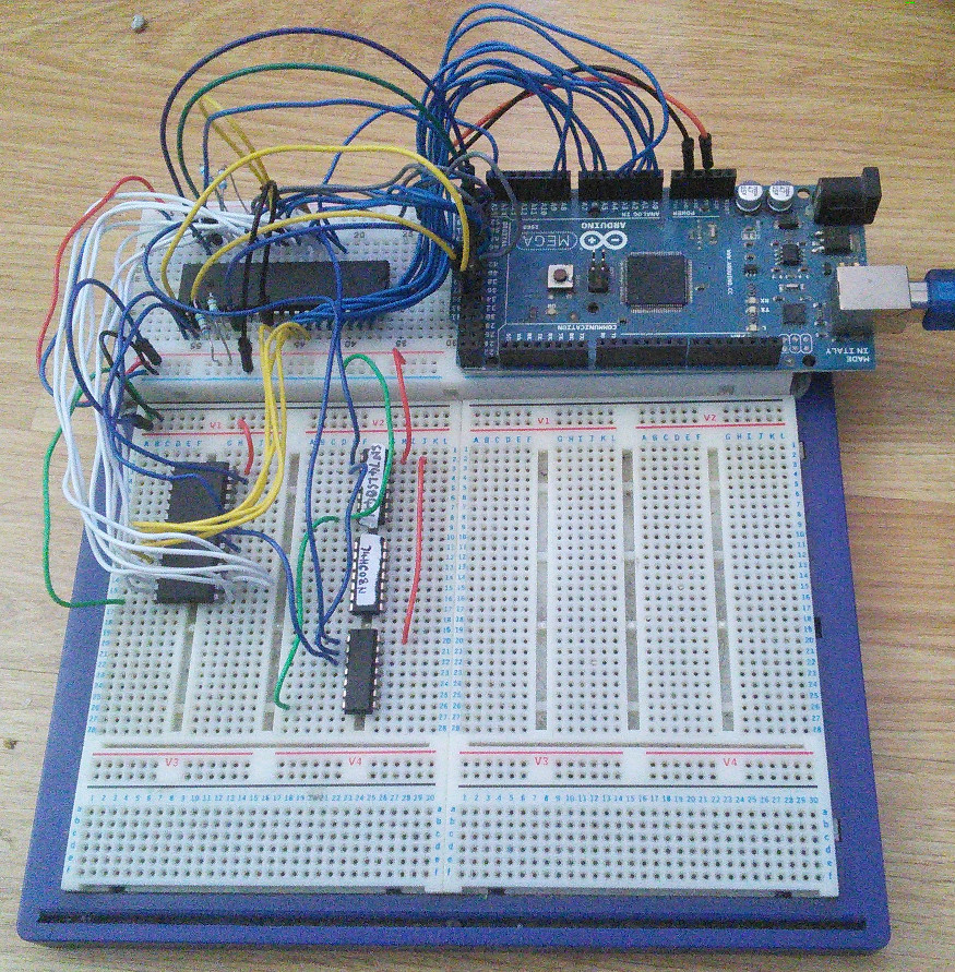
#     #    #    ######   #####     #
 #   #    # #   #     # #     #   ##
  # #    #   #  #     # #        # #
   #    #     # ######  #          #
   #    ####### #   #   #          #
   #    #     # #    #  #     #    #
   #    #     # #     #  #####   #####
I've always had the dream of building, even designing my own computer, and somehow the "lego" assembly that is a modern PC build has never quite satisfied... While tidying various components into a new case (anything is better than a broken cardboard box!) I happened across a Z80(8mhz!) an eeprom (8k) and even 32KB of static ram. Not having any fancy equipment like eprom writers or the like, I decided to go down the well worn route of using a micro controller to act as support for the Z80, even including the clock... If you look in the photo you can see the top breadboard with Arduino which comprised my initial experiments. I've actually reached an early goal with the project in that a can write and read back a few bytes from the eeprom, hence the post! (the eeprom is the almost Z80 sized chip on the left of the lower breadboards) [caption id="attachment_1077" align="alignleft" width="271"]
 click to embiggen[/caption]
Looking at the diagram you can see how I wired the Z80 to Arduino to get it to work, the connections used on the Arduino are frankly arbitrary, but there are four connections on the Z80 that are required to enable the Z80 to run, mainly to do with bus arbitration and interrupts. I think I used a 330Ω resistor (because that what I had to hand) to pull these pins high, I've seen people use 1K and even 3K or more for this and I guess I'll look again at this when I get round to putting some of the stuff on an actual circuit board!
Bugs not withstanding (and we'll say nothing about the string overflow issue! ahem) the control software on the Z80 wasn't that hard to put together, after sending a clock pulse it checks the state of the various control pins and the address bus and puts the appropriate value on the data bus (an array of bytes is used to look up memory reads). Initially all the control software could do was supply the Z80 with data sufficient to run a simple program that added two numbers and wrote the result to a memory location, the arduino would report via the serial connection to my laptop any writes to the specific address, locking up when halt signal came (not the way to put a Z80 into low power mode, but with no clocks at least its not thrashing about potentially running through the whole memory map repeatedly (not that I suppose it really matters)
If I'm honest I wasn't sure that even this simple experiment would work, and while it didn't exactly work first time, in short order I was happy indeed that my chosen route to bootstrapping my design was one that would actually work... You can read more about the details of my initial experiment here
Of course there have been additions to the control software on the Arduino, to allow serial output via Z80 in/out instructions (the Arduino then passing it on to its serial interface) I've also implemented a rudimentary debug mode that dumps the state of the address and data bus as well as reporting when some special feature like IO ports are in use, while this can help, as you don't have direct access to registers (in particular the PC) its probably less useful than you'd think.
Before micro controllers were readily available, I was always stuck with a chicken and egg situation, without some eprom "burner" I was stuck with (if you could find them) some one supplying you with a ready blown chip, of course this would leave you with whatever hardware design the software assumed - at least a serial IO and possibly more... and then of course there is the cycle of debug / code that doesn't sound fun if you're pulling a chip (even from a ziff socket) and re-burning it.
I have found it useful to use a very simple Z80 emulator / SDK that I'd put together runZ80 which allows a machine to be configured from devices provided by custom plugins, this way you're not stuck to someone else's design for a machine and you can try out your own ideas.
At the moment the eeprom sits at 0x8000 in the memory map this allows selection of the chip (via its chip enable) from the highest bit of the address bus, obviously as the CE pin is expecting an active low, A15 needs inverting, and as a signal on WR or RD might not just be for memory, you also have to look at MREQ too. Dealing with RD and WR are easy as there are complimentary pins on the eeprom. However I needed to combine the inverted A15 and the active low MREQ, and I'll hold up my hand here and admit that without thinking (properly) I put a 74LS08 in the breadboard till it dawned on me you can't AND two active low signals, if you think about it you have to OR them together...
So now I have the means to write to an eeprom I can at least write some kind of monitor software. In future I want to further reduce the reliance on the Arduino rather than the micro controller being in overall control I want it to be strictly support, possibly interfacing an SD card, this means replacing the clock source I'm thinking 1Mhz on the breadboard and maybe later once its on some Veroboard try it at 4Mhz (I can't see why anyone would need anything faster than that!) other plans include some kind of 128x64 LCD and some kind of input maybe even keyboard.
I still can't decide if I want just a simple machine code monitor, or if I should have some higher level language with the ability to set up and run machine code routines - which could leave the avenue open for a self contained machine that doesn't need to be programmed with my laptop...
Lots to do, but its nice to eventually see some gradual if slow progress...
click to embiggen[/caption]
Looking at the diagram you can see how I wired the Z80 to Arduino to get it to work, the connections used on the Arduino are frankly arbitrary, but there are four connections on the Z80 that are required to enable the Z80 to run, mainly to do with bus arbitration and interrupts. I think I used a 330Ω resistor (because that what I had to hand) to pull these pins high, I've seen people use 1K and even 3K or more for this and I guess I'll look again at this when I get round to putting some of the stuff on an actual circuit board!
Bugs not withstanding (and we'll say nothing about the string overflow issue! ahem) the control software on the Z80 wasn't that hard to put together, after sending a clock pulse it checks the state of the various control pins and the address bus and puts the appropriate value on the data bus (an array of bytes is used to look up memory reads). Initially all the control software could do was supply the Z80 with data sufficient to run a simple program that added two numbers and wrote the result to a memory location, the arduino would report via the serial connection to my laptop any writes to the specific address, locking up when halt signal came (not the way to put a Z80 into low power mode, but with no clocks at least its not thrashing about potentially running through the whole memory map repeatedly (not that I suppose it really matters)
If I'm honest I wasn't sure that even this simple experiment would work, and while it didn't exactly work first time, in short order I was happy indeed that my chosen route to bootstrapping my design was one that would actually work... You can read more about the details of my initial experiment here
Of course there have been additions to the control software on the Arduino, to allow serial output via Z80 in/out instructions (the Arduino then passing it on to its serial interface) I've also implemented a rudimentary debug mode that dumps the state of the address and data bus as well as reporting when some special feature like IO ports are in use, while this can help, as you don't have direct access to registers (in particular the PC) its probably less useful than you'd think.
Before micro controllers were readily available, I was always stuck with a chicken and egg situation, without some eprom "burner" I was stuck with (if you could find them) some one supplying you with a ready blown chip, of course this would leave you with whatever hardware design the software assumed - at least a serial IO and possibly more... and then of course there is the cycle of debug / code that doesn't sound fun if you're pulling a chip (even from a ziff socket) and re-burning it.
I have found it useful to use a very simple Z80 emulator / SDK that I'd put together runZ80 which allows a machine to be configured from devices provided by custom plugins, this way you're not stuck to someone else's design for a machine and you can try out your own ideas.
At the moment the eeprom sits at 0x8000 in the memory map this allows selection of the chip (via its chip enable) from the highest bit of the address bus, obviously as the CE pin is expecting an active low, A15 needs inverting, and as a signal on WR or RD might not just be for memory, you also have to look at MREQ too. Dealing with RD and WR are easy as there are complimentary pins on the eeprom. However I needed to combine the inverted A15 and the active low MREQ, and I'll hold up my hand here and admit that without thinking (properly) I put a 74LS08 in the breadboard till it dawned on me you can't AND two active low signals, if you think about it you have to OR them together...
So now I have the means to write to an eeprom I can at least write some kind of monitor software. In future I want to further reduce the reliance on the Arduino rather than the micro controller being in overall control I want it to be strictly support, possibly interfacing an SD card, this means replacing the clock source I'm thinking 1Mhz on the breadboard and maybe later once its on some Veroboard try it at 4Mhz (I can't see why anyone would need anything faster than that!) other plans include some kind of 128x64 LCD and some kind of input maybe even keyboard.
I still can't decide if I want just a simple machine code monitor, or if I should have some higher level language with the ability to set up and run machine code routines - which could leave the avenue open for a self contained machine that doesn't need to be programmed with my laptop...
Lots to do, but its nice to eventually see some gradual if slow progress...