I chose NodeMCU's ESP8266 board, mainly because it was cheap on ebay but also because it seemed to have everything I needed (as many pins broken out as possible - more later and enough of a circuit to get started with)
Knowing it was compatible with not only NodeMCU's firmware (uses Lua) but also MicroPython and the Arduino SDK I knew I'd have plenty of options.
While I did have a go with MicroPython, in the end for more complex uses I just found coding it as if its an Arduino was easier (Surprising given I generally prefer Python to C and especially C++!), I guess its just what you've gotten used to...
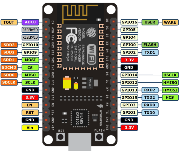
The biggest issue with using the Arduino SDK on a NodeMCU board has to be the pin names, for some odd reason rather than calling the pins GPIOxx in Lua they came up with yet another scheme! Oh the Joy! Fortunately when using Arduino SDK there is a direct correlation between the numerical pin number and the GPIO pin. There are a few convenience pin names like for example LED_BUILTIN is pin 16. Speaking of LED's there is also another LED connected to the USB serial tx pin (TX1 or better yet 2!)
Obviously with a WiFi enabled device blinking lights has to be controlled by web page served by the device itself, there is little difficulty in taking the ESP Arduino example and adding the second LED to it. WiFi access is made much easier by the fact that you can have the board connected to your own WiFi network and at the same time have to board behave like an access point (AP) with its own SSID and password. Having the board provide its own network is great for devices needing out of the box WiFi configuration, you connect your phone or tablet to the SSID and then provide the configuration information for your own WiFi AP.
The first device I hooked up was a SD card break out board, I have two boards but looking at one of them I think it has a 5v-3v3 level shifter on board, and as we're already at 3v3 I decided to use the board that was just a straight connection to the SD socket.
There is a bewildering range of names for the connections to an SD card to say the least! coupled with the fact that the NodeMCU board seems to have two SPI's labelled (at least some of the pins for one of the boards connections should be going to the "internal" flash - but I need to dig into that later)
The pins for the SD card are GPIO12-15 although CS could be anyone I chose to use 15 as it was next to the others
Starting from the bottom right (next to the flash button) there's a convenient 3v3 and GND pins you can use to power the SD card.
Skipping the next two pins (GPIO1 and 3 - one of the serial ports) there is GPIO15 (D8/TXD2/HSPICS) this wants to go to the Pin on your SD breakout board labelled CS / DAT3 / D3 or SS and there are probably other notations!
The next pin we want is GPIO13 (D7/RXD2/HSPID) which should go to DI / CMD / MOSI
GPIO12 (D6/HSPIQ) connects to DO / DAT0 / MISO
and finally GPIO14 (D5/HSPICLK) which goes to CK / CLK or even SCLK
You will need to edit the ESP8266 Arduino examples so they work with our chip select pin you may see
const int chipSelect = 4;this needs to be changed to 15 in our case, if a define isn't used look out for something like
if (!SD.begin(4)) {
again this needs changing to 15
What with all the confusion of pin names *sigh* I have to say I was maybe a little surprised and certainly delighted that it all worked first time.
It does look like there has been some decent work done on the SD library using such luxuries as folders, and not forgetting you don't suffer some of the issue that SPIFFS suffers from, I think SPIFFS is much better suited to references that don't change.
As well as obvious uses like data logging, serving files (via http) from the SD card, makes for easier updating and I might even get round to making a mini web application to allow editing / uploading directly (I've seen some but don't do just what I want!)