But what about the Z axis ? well a screw thread or better yet a lead screw has an exactly engineered thread, it may be slower than a toothed belt but you're very unlikely to find your Z axis needs calibrating...
That said there is a good chance that X & Y axis may well be just a touch out of calibration, while 1 or 2 percent is going to make a really tiny (i.e. no!) difference, on most small parts you want to print, when you want to print something larger you could well notice the difference. For example mortice and tenon joins of different prints, or even more exacting (believe it or not) interfacing with Legos, you will find a properly calibrated printer essential.
The first job is to take some
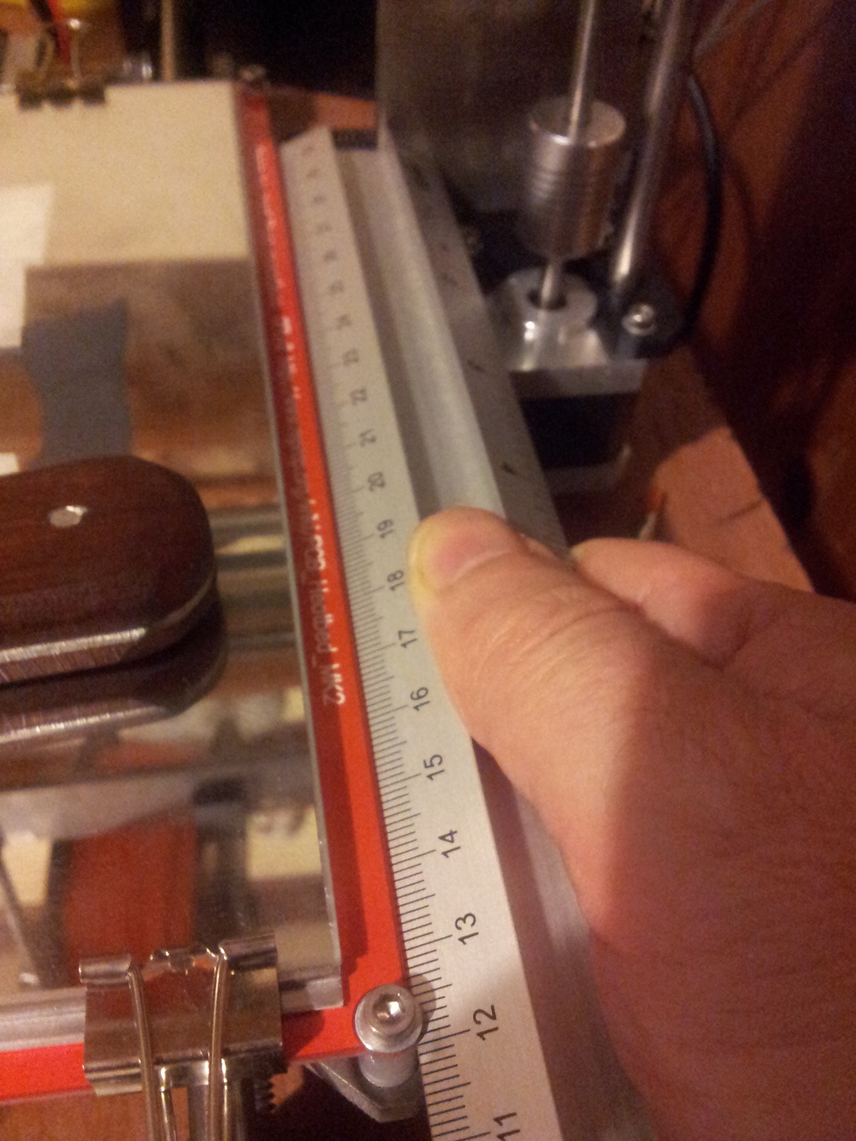
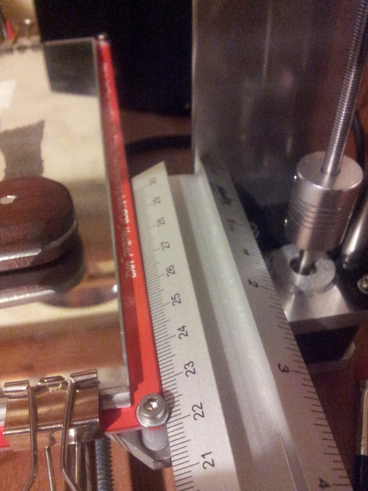
measurements, it doesn't matter if you don't have a fancy pants engineers ruler where zero is exactly on the end of the ruler, but it is handy if the end is square... for the Y axis its easy to use the bed itself as guide for the ruler and the frame as a stop. Using either the menu on the printer itself or software like Pronterface move the bed so its convenient to take a measurement, remembering that you need to be able to leave room to move the bed 100mm. Take your first measurement and then move the bed 100mm so you can take a second measurement. Subtract one from the other and if you end up with 100mm then happy days, meanwhile in the practical world ;) you might have a value like say 101mm, write this down as your actual Y axis movement.
Its no surprise that the X axis is rinse and repeat... find a convenient place to brace your ruler and make two measurement before and after an X axis 100mm move.
In case you are wondering what about all those 10mm-30mm calibration shapes on thingiverse...? Well they are a complete waste time, do you really think you could accurately measure 1% difference over 10mm? Personally I'm not so confident about my measuring ability.
Buried in the control menu of your printers LCD you should be able to find what your current steps per millimetre is for your X & Y axes with this information you have everything you need, so its time for a formula!
new steps per mm = old steps per mm * ( 100 / actual distance moved )Although its a simple formula lets work and example through, given a machine with 80.75 steps per mm setting and a measured movement of 101mm
N = 80.75 * ( 100 / 101 )
    80.75 * ( .9900990099 )
    79.95049504950495
Its not unusual for supplied firmware to come without EEPROM support, this is because when giving support for a kit, when the machine is power cycled it will be in a known state without any oddness from some errant setting in the EEPROM... Luckily because of the power of gcode this doesn't mean we have to recompile our firmware. A simpler method and just as effective is to embed the settings into each print, many slicers will allow you to put your own "custom" gcode into the print for example in Slic3r in the printer tab there is a text box for the code you wish to be put at the start of each print
M92 X79.950495 Y81.565657Inserting gcode like this with the appropriate values will make sure that your printer is "reset" to the correct calibration. Obviously you do need to check that everything has gone okay, two options, either repeat the measurement procedure above or if you're super confident print out a 10cm X 10cm L shape...